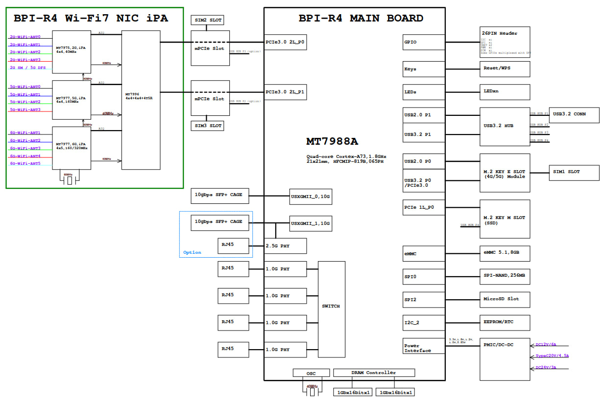
BPI-R4 is a high-performance router development kit from Banana Pi based on the MediaTek MT7988 (Filogic 880). It has unrivaled high performance IO scalability. It provides a wide range of high-speed interfaces from SFP+ to PCI-E(m.2).

The Fibocom FM350-GL is a 5G NR (SA/NSA) high speed (4670 Mbps DL / 1250 Mbps UL) 5G module that can be purchased at a relatively low price in the market today (2024). It is based on the Mediatek T700 chipset. And a full reference manual as well as an AT command manual can be found on the web.
In the first half of 2024, the Linux driver for the FM350-GL was merged into the mainline. Just last week, the driver for the BPI-R4-specific BPI-R4-NIC-BE14 Wi-Fi 7 module was also merged into OpenWrt’s latest Snapshot, which constitutes a necessary prerequisite for us to implement this project.
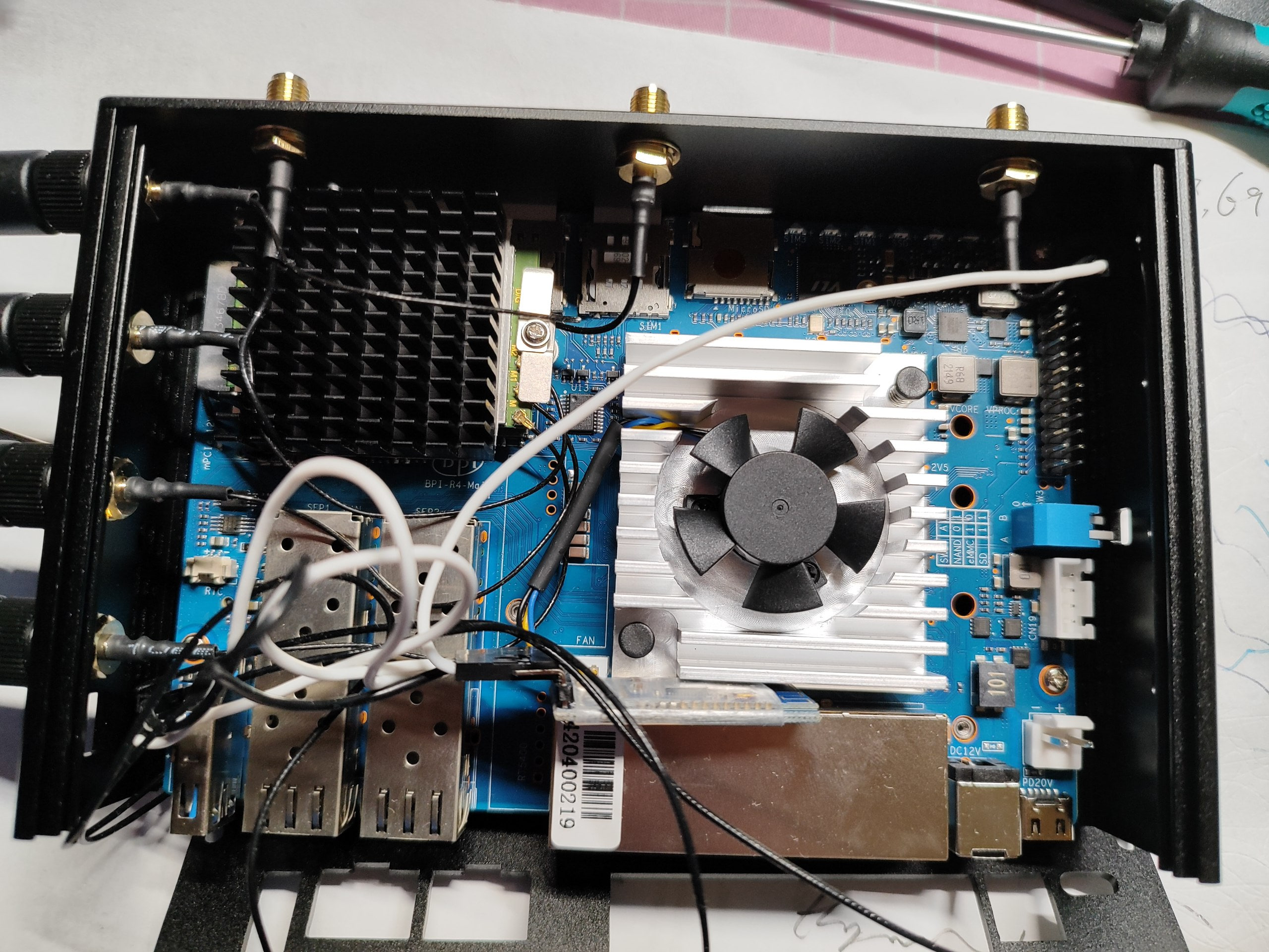
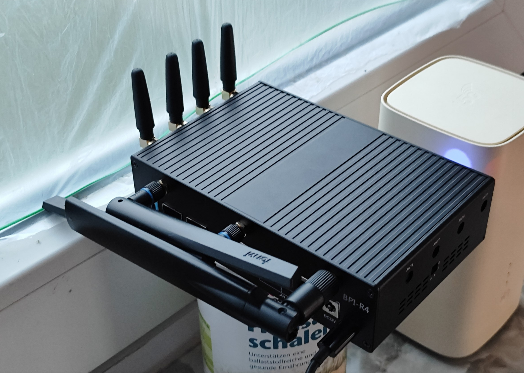
Installation of the module is very simple & straightforward, just insert it into the PCI-E2 slot labeled SIM1 and tighten the screws, remembering to install the proper antenna. Tip: Since the FM350 generates a lot of heat during operation, it is recommended to install a larger heatsink to ensure that no speed degradation occurs during operation due to overheating of the module.
Hardware readiness. Since neither the BSP-based firmware nor the OpenWrt Snapshot pre-compiled firmware will work properly with our current configuration, the next step is to compile the firmware.
First we install a compilation environment according to the official OpenWrt documentation (https://openwrt.org/docs/guide-developer/toolchain/install-buildsystem). I chose Ubuntu 24.04.3 Server.
Then pull the required source code according to this documentation (https://openwrt.org/docs/guide-developer/toolchain/use-buildsystem). And select the kernel and luci modules we need when make menuconfig.
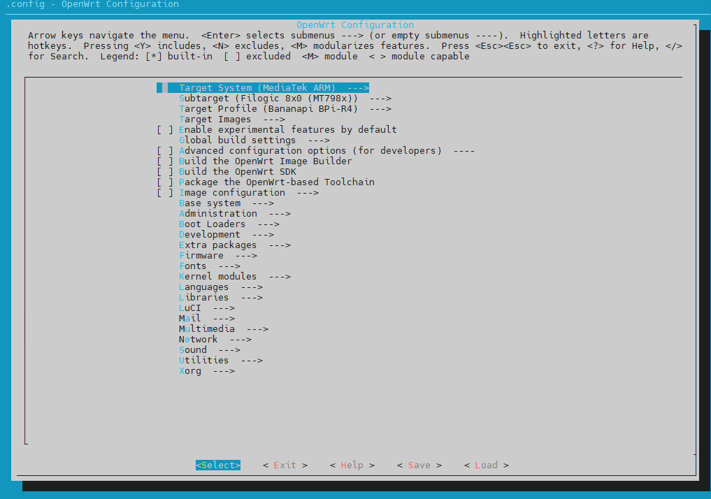
I checked the following:
mt7986-wo-firmware
mt7988-2p5g-phy-firmware
kmod-mtk-t7xx
kmod-phy-aquantia
kmod-sfp
kmod-wwan
kmod-usb-net-rndis
kmod-usb-serial
kmod-usb-serial-option
kmod-usb3
kmod-mt7915e
kmod-mt7986-firmware
kmod-mt7996-233-firmware
kmod-mt7996e
luci-proto-mbim
luci-proto-modemmanager
luci-proto-ncm
comgt
pciutils
usbutils
Then start the compilation. Then you can start the compilation in . /openwrt/bin/targets/mediatek/filogic/openwrt-mediatek-filogic-bananapi_bpi-r4-squashfs-sysupgrade.itb to find the compiled image.
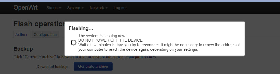
Flash it in.

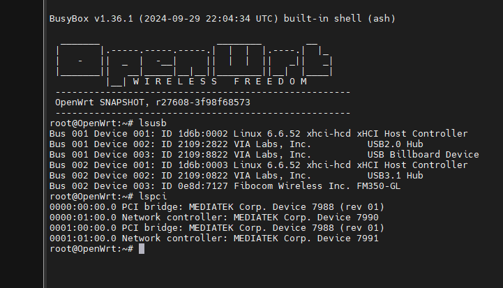
The first thing you can see is that the 3 Wi-Fi are working fine.
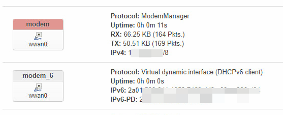
Since the FM350 is now working in PCI-E mode, create a new ModemManager interface inside the Interface tab. Then you can directly access the Internet.
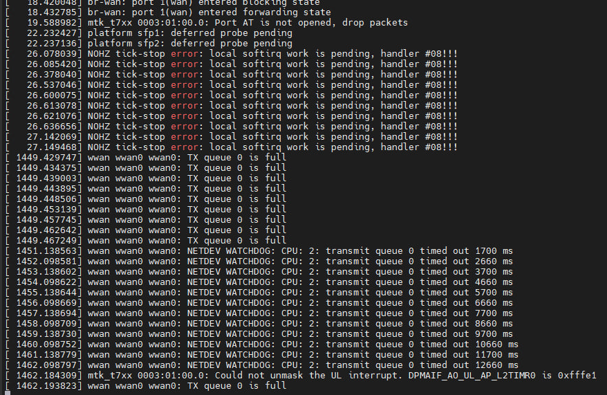
But it doesn’t last long, you’ll soon run into the problem shown in the image and it will soon lead to Kernel Panic and then an automatic reboot.
For this issue, I tried patch backporting the fix for the latest 6.11 kernel to Openwrt’s current 6.6 kernel. But the result is very little, just can alleviate, but not completely solve the problem of Tx Queue full.
https://github.com/torvalds/linux/commit/d785ed945de6955361aafc2d540d9bb7c6a69a65.patch
https://github.com/torvalds/linux/commit/7d5a7dd5a35876f0ecc286f3602a88887a788217.patch
For this, I first chose a workaround (for now) to get the FM350 to work in USB3 mode by modifying the dtsi to get around the PCI-E driver bug, which is why I had to go the extra mile to select various USB as well as NCM kmods before.
Now let’s go back to our compilation system. Execute the following command.
make -j$(nproc) defconfig download
Then modify the dtsi, path following
./build_dir/target-aarch64_cortex-a53_musl/linux-mediatek_filogic/linux-6.6.52/arch/arm64/boot/dts/mediatek/mt7988a-bananapi-bpi-r4.dts
/* M.2 key-B SIM1 */
&pcie2 {
	pinctrl-names = "default";
	pinctrl-0 = <&pcie2_pins>;
	status = "okay";
};
Modify line 290 to “disabled”.
/* M.2 key-B SIM1 */
&pcie2 {
	pinctrl-names = "default";
	pinctrl-0 = <&pcie2_pins>;
	status = "disabled";
};
Note that at this point in the compilation do not execute make clean or download, otherwise it will cause our changes to be overwritten.
make -j$(nproc) world
Then flash the newly compiled firmware obtained into the BPI-R4, and then power off and reboot. This is to completely reboot the chipset inside the FM350. Don’t ask me why, just do it, this is very important!
After poking around for a while, I’ve discovered that the best practice (for now) for using the FM350 in USB3 mode is to use a package called atc. Installation is very simple with the following command
wget https://github.com/mrhaav/openwrt/raw/master/atc/fib-fm350_gl/atc-fib-fm350_gl_2024-08-04-0.2_all.ipk
opkg install atc-fib-fm350_gl_2024-08-04-0.2_all.ipk
wget https://github.com/mrhaav/openwrt/raw/master/atc/luci-proto-atc_20230813-0.2_all.ipk
opkg install luci-proto-atc_20230813-0.2_all.ipk
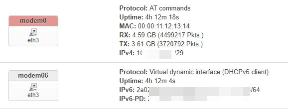
Similarly, create a new ATC proto port in the interface tab. And don’t forget to fill the APN.
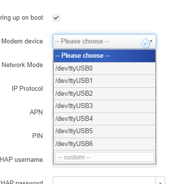
In my case the modem device is /dev/ttyUSB4, if it doesn’t work you can use minicom to send an AT command to confirm which ttyUSB is the real AT interface, it could be any of 0-7.
So far, you get a Wi-Fi7 router with 5G high-speed WWAN.
Thanks to my friend Ananas🍍 who provided me with various ideas.
继续阅读Using the Fibocom FM350-GL 5G module on Banana Pi BPI-R4